Surface Temperature Sensors: Ring Lug vs Flat vs Pipe Clamp
Nov 19, 2026Updated November 19, 2026.
| Surface | Mount that fits | Focusens series |
|---|---|---|
| Bolted joint, busbar, motor frame, screw hole in a heat sink | Ring lug, M3 to M12 hole | MFP-2 ring lug sensor, 3-wire version |
| Flat plate, power supply, heat-sink face | Flat pad, insert or thin film | MFP-2 flat sensor, insert type, MFP-1 thin film |
| Pipe 9.5 to 25 mm across | Curved pipe clamp with stainless clip | MFP-7 pipe clamp sensor |
| Pipes of mixed sizes, wet or underfloor | Adjustable overmoulded strap | IP68 pipe clamp sensor, MFE-1 with extension chain |
Series, hole sizes and clip sizes as listed on the linked Focusens product pages.
A ring lug temperature sensor suits any point where a bolt or screw already clamps metal to metal, because the fastener supplies the contact pressure and no adhesive is needed. A flat pad needs a flat face and something to press it down. A pipe needs a clamp curved to its diameter or a strap that adjusts. The surface decides the mount. Temperature range, and whether the sensor must come off again, then decide between the options left.
| Mount | Typical uses (product page) | How it is held | Removal | Rated range (product page) |
|---|---|---|---|---|
| Ring lug, MFP-2 | Motors, heat sinks, lithium battery protection, HVAC, projectors | Bolt or screw clamping force | Unbolt and refit | −30 to 150 °C (p67) |
| Flat pad or insert, MFP-2 | Power supplies, heat sinks, refrigerators | Clamp plate, screw or thermal epoxy | Removable unless bonded | −30 to 150 °C (p65) |
| Thin film, MFP-1 | Heating blankets, mats and pads | Adhesive or laminated in | Usually permanent | −30 to 125 °C (p170) |
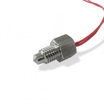
| Curved pipe clamp, MFP-7 | Underfloor heating, water heaters, wall-hung boilers | Stainless spring clip | By hand | −30 to 120 °C (p86) |
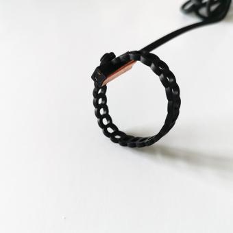
| Adjustable strap, MFE1D or MFE-1 | Floor heating, water pipes, heat pumps | Self-locking chain | By hand | −30 to 120 °C, MFE1D (p169); −40 to 105 °C, MFE-1 (p53) |
One mismatch to avoid is a flat pad strapped to a small pipe. It touches along one line, and the next section shows that this costs about as much as a dry, uneven joint. If none of the five mounts fits your surface, change the surface first: tap a hole for a lug or machine a flat for a pad.
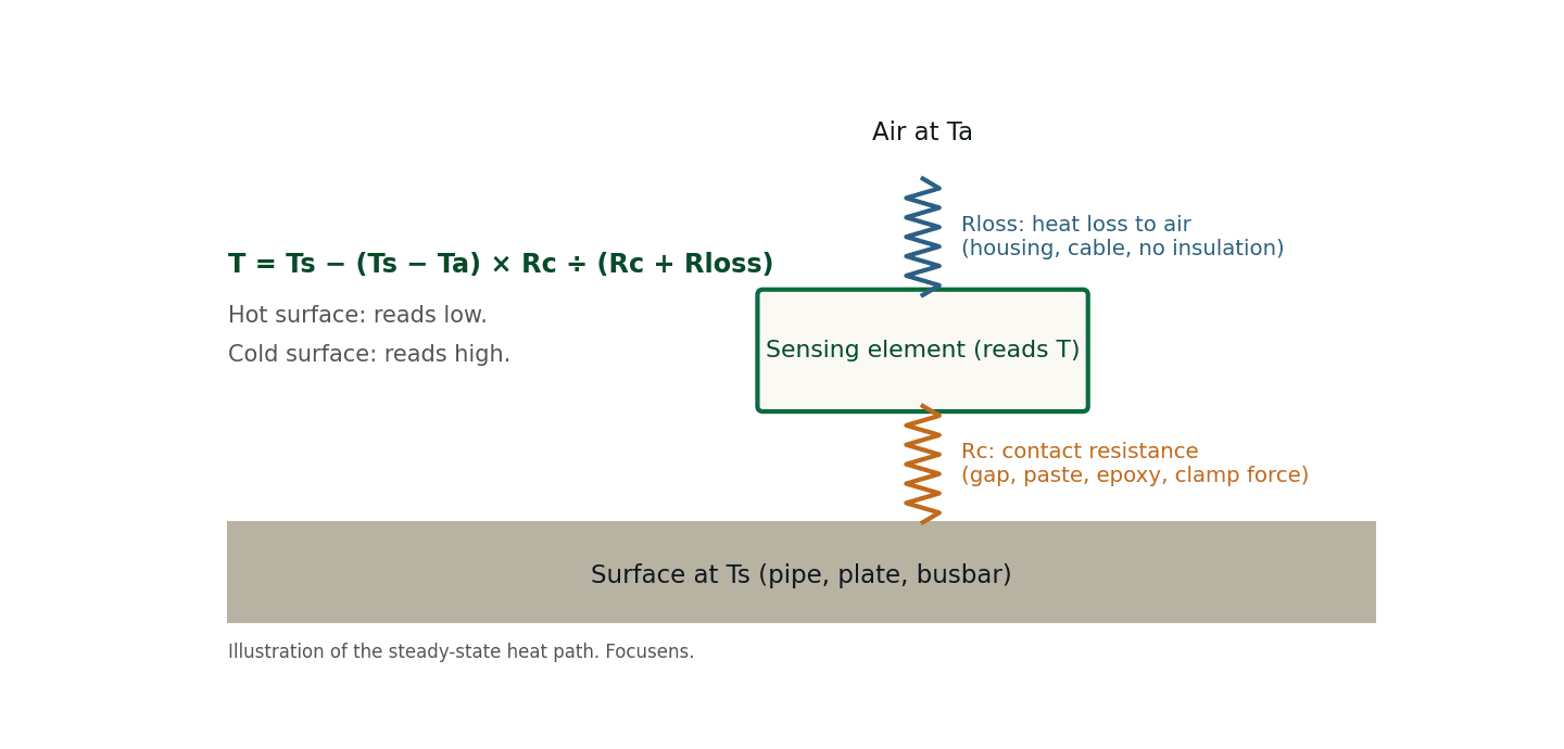
A surface temperature sensor sits between two temperatures, the surface it touches and the air around it, and two thermal resistances decide where its reading settles. Heat flows in from the surface through the contact resistance Rc: the gaps, paste or epoxy between sensor and surface. Heat flows out to the air through the loss resistance Rloss: the housing, the cable and anything that is not insulated. In steady state the reading is:
T = Ts − (Ts − Ta) × Rc ÷ (Rc + Rloss)
where Ts is the surface temperature and Ta the air temperature. On a hot surface the sensor reads low; on a cold one it reads high. The error grows with the difference between surface and air, so at room temperature every mount reads right, good or bad.
To put numbers on the formula we took the heat-loss path from the dissipation factor on our product pages, at least 2.5 mW/°C for the MFP-2 ring lug (p67), which gives Rloss = 1 ÷ 0.0025 W/K = 400 K/W. The pages give that figure as a minimum, so the real loss path can be shorter; the "4 × the heat loss" column below covers that case. Contact resistance is gap thickness divided by conductivity and area, here for a 6 × 15 mm face, the face of our MFE-1A flat probe. Air conducts 0.0262 W/m·K at 25 °C (Engineering ToolBox), MG Chemicals 860 silicone paste 0.7 W/m·K (MG Chemicals) and MG Chemicals 8329TCS thermal epoxy 1.4 W/m·K (MG Chemicals).
| Mount and interface | Contact resistance | Offset, 60 °C surface, 25 °C air | Same, with 4 × the heat loss | Offset, 7 °C pipe, 25 °C air | Contact time constant, 1 g copper body |
|---|---|---|---|---|---|
| Flat face on flat metal, dry, 10 µm average gap | 4.2 K/W | −0.37 K | −1.42 K | +0.19 K | 1.7 s |
| Flat face on flat metal, dry, 50 µm gap | 21.2 K/W | −1.76 K | −6.12 K | +0.91 K | 8.3 s |
| Same 50 µm gap filled with silicone paste | 0.79 K/W | −0.07 K | −0.28 K | +0.04 K | 0.3 s |
| Same 50 µm as a thermal epoxy bond line | 0.40 K/W | −0.03 K | −0.14 K | +0.02 K | 0.2 s |
| Flat pad on a 15 mm pipe, dry, line contact | 22.8 K/W | −1.89 K | −6.49 K | +0.97 K | 8.9 s |
| Flat pad on a 15 mm pipe, paste-filled | 0.85 K/W | −0.07 K | −0.30 K | +0.04 K | 0.3 s |
| Curved clamp on a 15 mm pipe, dry, 10 µm gap | 4.2 K/W | −0.37 K | −1.42 K | +0.19 K | 1.7 s |
| Curved clamp on a 15 mm pipe, with paste | 0.16 K/W | −0.01 K | −0.06 K | +0.01 K | 0.1 s |
Our calculation. Heat loss 400 K/W from the product-page dissipation factor (the pages do not state the medium); "4 × the heat loss" is 100 K/W, a what-if for moving air, a heavy cable or no insulation. Flat pad on a pipe: 6 mm wide pad, gap starting at 10 µm and widening with the pipe's curve. Time constant = contact resistance × heat capacity of 1 g of copper, 0.39 J/K (Engineering ToolBox). The sensor's own body, a polymer tip and the cable add to every figure; these are the contact's share, calculated, not measured on a Focusens part.
A dry 50 µm gap costs about 1.8 K on a 60 °C surface, several times the ±0.2 °C at 25 °C of a ±1 % 10 kΩ NTC element (RTD vs thermistor tolerance table). Burrs, paint and a bowed face all hold a sensor off the metal, and the 50 µm row shows what such a gap costs. Filling the same gap with paste brings the offset under 0.1 K, and a flat pad on a 15 mm pipe behaves like the 50 µm dry gap while a curved clamp of the right size behaves like the 10 µm one. When the air moves, the cable is heavy or nothing covers the sensor, the loss path gets shorter and the same dry gap costs about 6 K. On a 7 °C chilled-water pipe in a 25 °C room the sign flips and the sensor reads warm. The measuring current adds a small self-heating term on top, worked out in our thermistor wiring guide.
Real installations can run larger than the table. On externally heated pipes and vessels near 500 °C, a spring-loaded flat-tip thermocouple can read well below the surface temperature. In the formula, a reading 10 to 20 % closer to ambient would mean Rc ÷ (Rc + Rloss) of 0.1 to 0.2. The table reaches that share only in the dry 50 µm gap and dry line-contact rows with 4 × the heat loss (about 17 to 19 %), while every paste and epoxy row stays under 1 %. The model covers the contact alone; at 500 °C, radiation and heat conducted along the sheath also pull the tip toward ambient, which is one reason a field reading can sit below the calculated one.
To work out your own case, you need three numbers:
For a flat pad on a 90 °C heat sink inside a 40 °C cabinet, with a dry 50 µm gap under a 6 × 15 mm face, Rc is 21.2 K/W and the sensor reads about 2.5 K low; with paste in the gap, Rc is 0.79 K/W and the offset falls to about 0.1 K (our calculation).
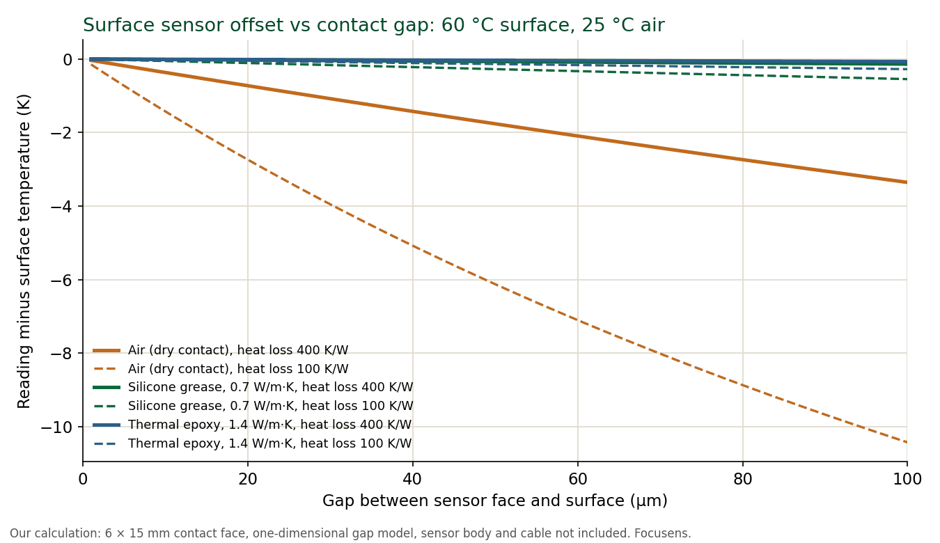
Fix the contact before you pay for a tighter element tolerance: on a dry, uneven face the mount can cost more than the element's whole tolerance band.
The MFP-2 and MFP-7 product pages linked in the first table list T0.63 ≤ 30 s for Focusens ring-lug, flat and pipe-clamp sensors, measured in water flowing at 0.4 m/s. T0.63 is the time to reach 63.2 % of a temperature step, which for a first-order sensor is one time constant τ. The other points of the curve follow from it:
| Share of the step reached | Time in time constants | If τ = 30 s |
|---|---|---|
| 50 % | 0.69 τ | 21 s |
| 63.2 % | 1.00 τ | 30 s |
| 90 % | 2.30 τ | 69 s |
| 99 % | 4.61 τ | 138 s |
Our calculation for a first-order response: time = −τ × ln(1 − share reached).
Water at 0.4 m/s reaches the probe from every side. On a surface, heat enters through one face, so expect a surface sensor to respond more slowly than its water figure. The contact adds its own lag: a dry 50 µm gap adds about 8 s of time constant to a 1 g copper body, and paste cuts that to 0.3 s (our calculation, table above). Response figures are comparable only when medium and flow are the same; our thermistor assembly selection guide shows which Focusens series are rated in still air instead of water.
On an insulated copper pipe the penalty is smaller than this reasoning suggests. With thermal grease in the joint and insulation over it, a strap-on sensor follows the water about as fast as a sensor in a well, because a well slows a probe too. On a heat sink, a ring-lug thermistor on one face lags a bead thermistor on the other by a few seconds. With paste, the contact's own share of the lag in our calculation is well under a second, so most of that delay comes from the sensor body and the part being measured. If your control loop needs a surface response figure, ask for one measured on your mount and surface.
A ring lug temperature sensor measures the part under the bolt, so the bolt has to clamp the lug straight onto the surface you care about. The MFP-2 ring lug puts an NTC element, with R25 and B value to order, inside a copper or tin-plated copper lug with PVC or PTFE (Teflon) wire, rated −30 to 150 °C (p67), with holes for M3 to M12 screws (p62).
A dry lug on a small heated block shows the range to expect. Take ring-terminal thermocouples on a 3D-printer hot end that read about 30 °C below a probe pushed into the heater block. With the block roughly 225 K above room air, the formula gives about 11 K for a dry 50 µm gap at 400 K/W heat loss and about 39 K with 4 × the heat loss (our calculation), so a 30 K shortfall fits a dry, poorly coupled lug. Two ring lugs screwed to the same heat sink should track each other closely. If one reads several degrees off after fitting, suspect damage from over-tightening its screw. Clamping force matters, but past the point of full contact more torque only risks the sensor.
A 3-wire version of the MFP-2 ring lug is listed for voltage-protection wiring (p63); check which conductor is which on the drawing for your order. If the only bolt nearby clamps a bracket, a cover or a cable shoe rather than the hot part, the lug will read the bracket, so find or tap a hole in the part itself.
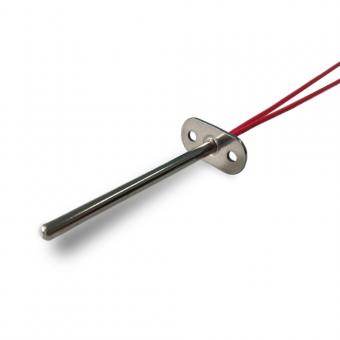
A flat surface temperature sensor reads well only when its face and the surface are both flat and pressed together, because in the table above the gap sets most of the error. Focusens makes four flat formats:
A clamp plate or screw with a thin layer of paste gives a joint you can open and refit. Thermal epoxy makes a permanent one; MG Chemicals 8329TCS, for example, cures in 1 hour at 80 °C (MG Chemicals). An insert sensor in a drilled hole touches all round, but the hole clearance is an air gap like the ones in the table, so fill it with paste or epoxy. A flat pad on a curved surface touches along a line; on a 15 mm pipe that puts it in the same class as a 50 µm dry gap. On a flat surface, pay for flatness and filler first and a tighter thermistor second.
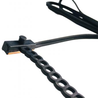
A pipe clamp temperature sensor reads the pipe wall, and the wall sits between the fluid inside and the air outside. The MFP-7 pairs an NTC sensor with a curved face and a separate stainless steel clip, with standard clip sizes of 9.5, 12.7, 19 and 25 mm (p86), which are 3/8, 1/2, 3/4 and just under 1 inch (our conversion). The strap-on alternatives are the MFE1D, overmoulded in TPE with or without a copper tip on a 110 mm adjustable chain that takes extra chains for larger pipes, rated −30 to 120 °C (p169), and the MFE-1 for 1/2" pipe with an extra chain for bigger diameters, rated −40 to 105 °C (p53).
Which of the two to specify is covered in pipe strap vs clamp-on temperature sensors. Three points from the formula apply to both:
A surface reading lags the fluid, and offsets from it whenever the air is at a different temperature. Where a threaded port exists, a screw-in probe such as the G1/2, G1/4 or G1/8 MFP-7 pipe sensor measures the fluid itself, and our buyer's guide to strap and clamp-on sensors covers how each one fails over time and when to stop using surface mounts. Resolving a rise of less than 1 °C across a small solar collector is one case where sensors on the pipe surface are not accurate enough, and an immersion probe in a tee is the fix. If the reading goes on an invoice or into a control limit tighter than the offsets in the table, put a probe in the flow.
Silicone thermal paste conducts about 27 times better than the air it replaces (0.7 against 0.0262 W/m·K), which is why it removes most of the contact error in the table. Thermal epoxy doubles the conductivity again and fixes the sensor for good.
| Interface | Thermal conductivity | Service temperature | Removable | Use when |
|---|---|---|---|---|
| Dry contact, air in the gaps | 0.0262 W/m·K at 25 °C (Engineering ToolBox) | no limit from the interface | yes | faces are machined flat and clamped hard, or the sensor is temporary |
| Silicone paste, e.g. MG Chemicals 860 | 0.7 W/m·K | −40 to 200 °C (MG Chemicals) | yes; re-apply after removal | a bolt, clamp or clip holds the sensor and you may refit it |
| Thermal epoxy, e.g. MG Chemicals 8329TCS | 1.4 W/m·K | not stated on the product page (MG Chemicals) | no | nothing else can hold the sensor, or vibration would walk a clamp loose |
A filler only helps while it is thin. Its resistance is thickness divided by conductivity and area, so 50 µm of paste is 0.79 K/W on a 6 × 15 mm face and 500 µm would be ten times that (our calculation). Squeeze the paste out to a thin line under clamping pressure rather than building a blob.
A dry joint is acceptable only where the faces are flat enough to leave an average gap near 10 µm and the 0.4 K of the first table row is within your budget. In a thermowell surrounded by liquid the loss path is long, so in the formula a gap there mostly costs time. On an exposed surface the loss path is open, so the same gap costs degrees as well as seconds. Use paste on any surface you have not machined flat yourself.
Each step adds to the one before. On hydronic heating pipes, paste and tape alone leave the reading slightly off. Wrapping insulation over the sensor helps, and a heat-transfer epoxy under insulation is better again, though the reading still drifts when the circulator stops.
Place a surface temperature sensor on bare metal of the part whose temperature you control, then mount it in six steps, each of which shrinks one term of the formula:
A strap-on reading that looks far off is worth checking at the mount before the controller is blamed. If a strap-on system sensor on a boiler reads many degrees below both the inlet and the outlet, strap it tightly with a hose clamp, insulate over it and check it against ice water. Mixing at the header can cause the same gap, so check where the sensor sits as well.
For probes that go into a hole, a fluid or a threaded port, see our thermistor mounting guide. Only step 6 shows whether steps 1 to 5 worked.
For continuous monitoring, the best way to measure surface temperature is a contact sensor pressed onto bare metal with a thin layer of paste or epoxy and insulated over; that keeps the contact share of the error to tenths of a degree or less in our calculation. A handheld infrared thermometer suits spot checks, but its reading depends on the emissivity setting matching the surface, and bare shiny metal is the hardest case. On low-emissivity metals such as copper or aluminium an infrared gun mostly reads reflected surroundings.
A surface temperature sensor should be placed on the part whose temperature you control, on clean bare metal, under any insulation, and away from brackets, fittings and heaters that run at a different temperature. On a pipe, mount it on a straight run of the pipe itself rather than on a valve or fitting body.
To mount a temperature sensor on a surface, clean the spot to bare metal, add a thin layer of paste or thermal epoxy, fix the sensor with its bolt, clip or strap, lay the first part of the cable along the surface and insulate over it. Then check it against a reference thermometer at working temperature, not at room temperature.
A surface temperature sensor needs thermal paste wherever the faces are not machined flat and clamped hard. In our calculation, paste cuts the offset of a 50 µm dry gap from 1.76 K to 0.07 K on a 60 °C surface; where the average gap is about 10 µm, the dry offset is about 0.4 K, so paste is optional there.
A pipe temperature sensor reads lower than the water because the pipe wall and the sensor both lose heat to the surrounding air, and contact resistance lets the sensor drift toward air temperature. Add paste, insulate over the sensor and check that the clamp size matches the pipe. On a chilled-water line the same effect makes the sensor read high.
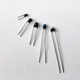
An NTC thermistor gives the largest signal per degree near room temperature, and every Focusens surface sensor on this page uses one, rated between 105 and 150 °C at the top end. A PT100 or PT1000 RTD suits wider ranges and tighter interchangeability, and a thermocouple covers the highest temperatures. The comparisons are in RTD vs thermistor, thermistor vs thermocouple and thermocouple vs RTD.
A quote for a surface temperature sensor comes back right the first time when it states the mount, the surface and the temperatures on both sides of the sensor:
Focus Sensing and Control Technology Co., Ltd. holds ISO 9001:2015 and IATF 16949:2016 certificates: ISO 9001:2015 from NOA, certificate 05126Q01105R001, valid to 2029-03-30, and IATF 16949:2016 from AENOR, certificate RA02-0749/2025, valid to 2028-09-13. Send us the list above or your drawing and we will propose a part.
Product ratings are from the linked Focusens product pages as of November 2026. Conductivities come from Engineering ToolBox and MG Chemicals. Offsets and response times marked "our calculation" are computed from those inputs and are not bench measurements on a Focusens part.
No.1 XiSan Road, Electromechanical Industry Park , High&New Tech.Zone. Hefei,Anhui,China
tel : +86-551-69109668
Whatsapp : +86-13339100504
e-mail : info@focusens.com
Skype : melodyliu520






 +86-551-69109668