How to test an NTC thermistor with a multimeter
Sep 05, 2026Set the meter to ohms, disconnect at least one lead of the thermistor, and measure at room temperature. A healthy NTC reads close to its rated R25.
Then warm it and watch the reading fall, or chill it and watch the reading rise. An open circuit, a near short, or a reading that does not move with temperature means the part has failed.
That answers the question. What follows is how to know what “close to R25” should be for your specific part, why a room-temperature check passes a drifted sensor, and when a measurement taken without unsoldering can be trusted.
Published 5 September 2026. Reviewed by the Focusens technical department.
Kill the power and let the equipment sit. Resistance measurement injects the meter's own small current, so a live circuit gives a meaningless reading and can damage the meter.
Watch for stored energy. Power supplies, motor drives and anything with a large bulk capacitor hold a charge after the mains is disconnected. Wait for the discharge indication the equipment provides, or check across the bus with the meter on volts before switching to ohms.
Note the ambient temperature. Every judgement below is relative to the temperature the thermistor is actually at, not to the number printed on the datasheet.
You need a digital multimeter with an ohms range, a way to change the part's temperature by a controlled amount, and the part's R25 and B value. A cup of iced water and a thermometer beats a hot air gun for this, because you know what temperature the part reaches.
“The resistance should change” is not enough to judge a part, because the amount it should change is set by the B value.
For a 10 kΩ thermistor with B25/85 = 3988, the Beta equation gives these ratios against its own 25 °C value. Terminology, test methods and the generic requirements for these devices are defined in IEC 60539-1:2022.
| Check point | Temperature | Resistance | Ratio to R25 |
|---|---|---|---|
| Iced water | 0 °C | 34.0 kΩ | 3.40 × |
| Cool room | 20 °C | 12.6 kΩ | 1.26 × |
| Rated point | 25 °C | 10.0 kΩ | 1.00 × |
| Held in the hand | 35 °C | 6.5 kΩ | 0.65 × |
| Warm water | 50 °C | 3.6 kΩ | 0.36 × |
| Boiling water | 100 °C | 680 Ω | 0.068 × |
Calculated from the Beta equation with R25 = 10 kΩ and B = 3988 K.
The ratios are not universal, because they follow B. Iced water gives roughly 2.9 × for a B3435 part, 3.4 × for B3988, and 3.7 × for B4300.
So a part that only doubles in iced water is suspect whatever its B value, while the difference between 3.4 and 3.7 tells you nothing without knowing which part you are holding.
Two things follow. Multiply rather than subtract when you sanity check a reading, since the ratio holds for any R25 with the same B. And if you do not know the B value, the iced-water test still tells you the part is alive and responding, just not whether it is accurate.
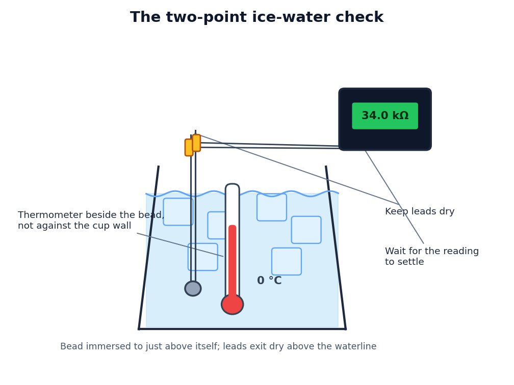
The two-point check. The ice bath fixes the reference at 0 °C, which a hot air gun cannot do.
A meter reading falls into one of nine patterns, and each points somewhere different.
| Reading | What it means | What to do |
|---|---|---|
| Near rated R25 at the measured ambient, moves correctly with temperature | Healthy | No action |
| Open circuit or overrange | Cracked bead or broken lead | Replace. Measure again at the sensor body to confirm the break is not in the cable |
| Near zero ohms | Short between conductors, often moisture in a connector or a crushed cable | Inspect and dry the connector. If the reading stays low with the sensor fully isolated, replace |
| Plausible value, no change when heated or cooled | Not a working thermistor. Either failed, or it is a fixed resistor | Confirm the part number before replacing |
| Resistance rises when heated | It is a PTC, not an NTC | Use the PTC procedure instead |
| Correct cold, wrong hot, or the reverse | Drift, or a wrong assumed B value | Two-point check, below |
| Correct but slow to respond | Thermal contact problem, not an electrical fault | Check mounting, thermal compound, immersion depth |
| Jumps or flickers while probing | Intermittent connection in the lead or crimp | Flex the cable while watching the meter. Reterminate |
| Reads high by a consistent small amount | Contact resistance at the probes or a long test lead | Null the meter leads, or subtract the leads' own resistance |
That last row matters more on low-resistance parts. Half an ohm of test-lead resistance is 0.005% of a 10 kΩ reading and can be ignored, but the same half ohm is 0.33% of the same part measured at 100 °C where it reads 150 Ω.
Null your leads before measuring anything under a few hundred ohms.
A thermistor that has drifted still reads a plausible resistance. It passes continuity, it responds to heat, and at room temperature it can look perfect.
The reason is the same one that hides a wrong B value: deviation is smallest at the reference point and grows with distance from it.
A 1% B error produces zero error at 25 °C and roughly 0.9 °C at 100 °C. Ageing behaves similarly. A single measurement near ambient is taken at exactly the temperature where the fault is least visible.
So take two points. Measure at ambient, then at a second temperature near the part's working range, and check both against the ratio table. Iced water is the practical second point because it is repeatable and free.
If the working range is high, boiling water gives you a second fixed point, with the caveat that it varies with altitude.
A part that is right at one point and wrong at the other has drifted or is not the part you think it is. A part that is wrong at both by the same proportion is more likely the wrong value entirely.
Why NTCs drift, and how mounting affects response, is covered in the NTC thermistor guide.
You can sometimes measure without unsoldering, and you need to know when the answer is trustworthy.
The problem is parallel paths. Any resistor, semiconductor junction or filter capacitor across the thermistor is measured with it, and the result is always lower than the true value. A 10 kΩ thermistor across a 10 kΩ divider resistor reads 5 kΩ, and nothing about that reading looks obviously wrong.
Unplugging a connector is usually enough, and it is quicker than desoldering. If the part is soldered down, lifting one leg breaks every parallel path at once.
An in-circuit reading is still useful for a rough go or no-go check. If the reading is a plausible fraction of the rated value and moves the right way with temperature, the sensor is probably alive.
Do not use an in-circuit number to judge accuracy, and do not conclude a part is out of tolerance without isolating it first.
Capacitance across the sensor also makes the reading creep upward for several seconds before settling. Wait for a stable number rather than reading the first value.
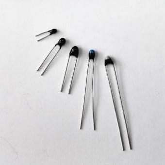
The procedure above covers two-terminal NTC thermistors, which is what most temperature sensors in appliances, vehicles, battery packs and HVAC equipment are. If resistance rises with heat, the part is a PTC and the pass criteria are different.
Motor protection PTCs in particular have a low, flat cold resistance and only change sharply within a few degrees of their rated switching temperature, so ordinary bench heating may never reach the transition. That procedure is in how to test a PTC thermistor with a multimeter.
If the part is unmarked and you do not know which you have, how to identify NTC and PTC thermistors is the place to start.
If the assembly has three or more wires, it is probably two sensors in one housing, or a sensor with a shield. Measure each pair in turn and expect one pair to read open.
If the part is a platinum RTD rather than a thermistor, resistance rises with temperature and moves by well under one percent per degree, so it looks almost fixed on a meter compared with an NTC. The resistance temperature detector guide covers those.
A sensor that passes every check above is telling you the fault is elsewhere. Check the wiring for an intermittent crimp by flexing the harness while watching the meter.
Check the controller's input configuration, since many accept several sensor curves and the wrong selection produces a wrong temperature from a perfectly good part.
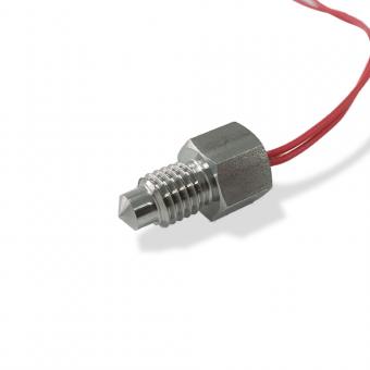
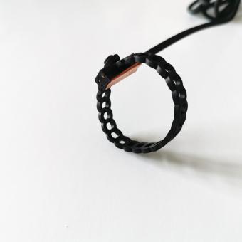
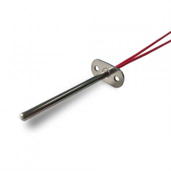
And check the mechanical mounting, because a sensor that has come loose from its surface reads air rather than the thing it is supposed to be measuring. Replacement probes and elements are in the NTC thermistor category.
The resistance values and ratios are calculated from the Beta equation, using the stated R25 and B value. They show the shape of a correct response and are not a datasheet for any specific part.
Check readings against the curve data for the part in front of you, and treat the ratios as a sanity check rather than a tolerance limit.
This page does not give a pass or fail tolerance band, because that depends on the part's own R25 and B tolerance, on how accurately you know the temperature at the moment of measurement, and on your meter's accuracy on the range in use.
No.1 XiSan Road, Electromechanical Industry Park , High&New Tech.Zone. Hefei,Anhui,China
tel : +86-551-69109668
Whatsapp : +86-13339100504
e-mail : info@focusens.com
Skype : melodyliu520






 +86-551-69109668